34+ frequency modulation block diagram
A modulation block diagram MBD is a graphical representation of a digital audio signal. Frequency modulation FM is the encoding of information in a carrier wave by varying the instantaneous frequency of the wave.

Difference Between Amplitude Modulation Am Vs Frequency Modulation Fm In How It Sends It S Radio Signal Amplitude Modulation I Ching Twitter Sign Up
There are the three key parameters of the modulation which is amplitude phase.

. Modulation index b k p A m BW 2k p A m 1f m Increasing frequency has. In analog frequency modulation such as radio broadcasting of an audio signal representing voice or music the instantaneous frequency deviation ie. Phase modulation is defined as the process of varying the phase of the carrier signal linearly with the instantaneous value of the message signal.
The technology is used in telecommunications radio broadcasting signal processing and computing. - March 16 2018. Amp and local oscllator and produces Intermediate.
1 shows block diagram of the modulation where the signal is modulated by the carrier signal. Frequency modulation FM is a technique in which the frequency of a transmitted waveform is varied according to the variations in the message wave. The waveforms of a message signal and the.
RECEIVER 41 Introduction 25 42 Sensitivity and Selectivity 25 4. 1 shows block diagram of the modulation where the signal is modulated by the carrier signal. The amplitude of each side frequency does not follow any simple.
It shows the various stages in a digital audio signals flow from the source audio input. The transmitted signal power all through the transmission stays as constant. When the frequency of the carrier wave varies with the amplitude of the message signal it is called frequency modulation.
Page 5 The distance between each of the side frequencies is equal to the frequency of the modulating signal fs. Phase-shift keying PSK is a digital modulation scheme that conveys data by changing or modulating the phase of a. Patch E08phasemodpd shown in Figure 515 shows how to use Pd to realize true frequency modulation part a and phase modulation part b.
Frequency Modulation FM is a form of modulation in which changes in the carrier wave frequency correspond directly to changes in the baseband signal. Phase modulation and FM. Example Commercial FM signals use a peak frequency deviation of f 75 kHz and a maximum baseband message frequency of fm 15 kHz.
It is a type of angle modulation a non-linear modulation process. For tone modulation. Unless the modulation frequency is increased the bandwidth is not increased and remains.
For tone modulation. Modulation index b Df f m BW 2k f A m f m PM. 1 shows block diagram of the modulation where the signal is modulated by the carrier signal.
It produces unmodulated signal or humming which always 455 KHz. It mixes the two signals coming from the RF. Psk modulation block diagram.
The FM is a very popular technique. There are the three key parameters of the modulation which is amplitude phase and frequency.

Frequency Shift Keying Fsk Modulation And Demodulation Electrical Projects Engineering Projects Circuit Diagram

Circuit Design Circuit Amplitude Modulation

Frequency Shift Keying Fsk Modulation And Demodulation Electrical Projects Circuit Diagram Data Transmission

Circuit Diagram Of Pulse Position Modulation Ppm Modulator In 2022 Circuit Design Circuit Diagram Positivity

Very Simple Fm Radio Receiver Circuit Circuitspedia Com

This House Fm Transmitter For Your Stereo Or Any Other Amplifier Provides A Good Signal Strength Up To A Distance O Fm Transmitters Transmitter Circuit Diagram

Fm Wireless Microphone Circuit Diagram Eleccircuit Com Circuit Diagram Electrical Circuit Diagram Circuit

Pam Modulator Or Demodulator Circuit Diagram Train Board Modulators

Am Fm Radio Fm Receiver Circuit Diagram Using Tea5710 Tea5710t Circuit Diagram Fm Radio Electronics Circuit

Fm Transmitter Circuit Using Transistors Gadgetronicx Circuit Diagram Fm Transmitters Electronics Circuit

Usb Fm Transmitter Circuit Fm Transmitters Electronic Schematics Transmitter

Frequency Division Multiplexing Block Diagram Communication System Block Diagram Systems Engineering
Fm Modulation System Fm Transmitters Communication System System
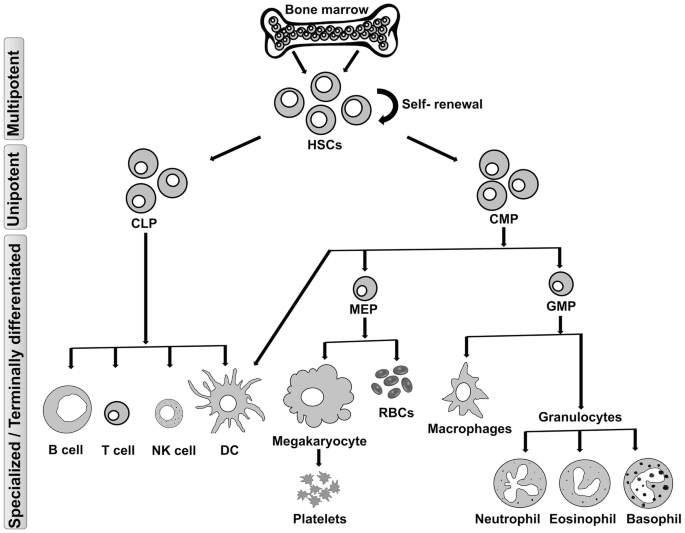
Differentiated Cells Derived From Hematopoietic Stem Cells And Their Applications In Translational Medicine Springerlink

Pin On Electronics

Figure 9 Top Amplitude Modulation Of Signal 1 By Signal 2 Figure 10 Bottom The Harmonic Spectrum Of Amplitude Modulation Writing Equations Block Diagram

Frequency Modulation Frequency Deviation Bandwidth Of Fm Wave Modu Frequencies Waves Chart